Parts
Waveguides
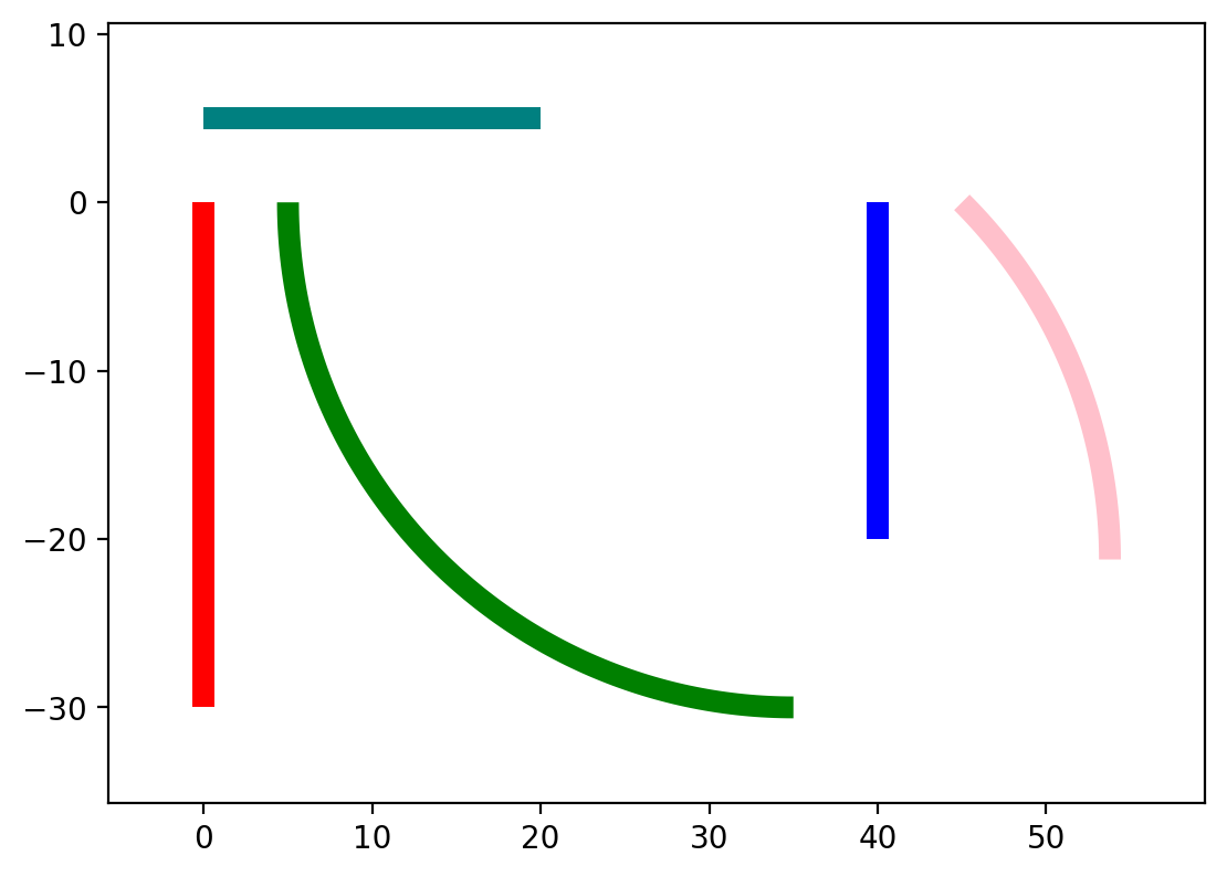
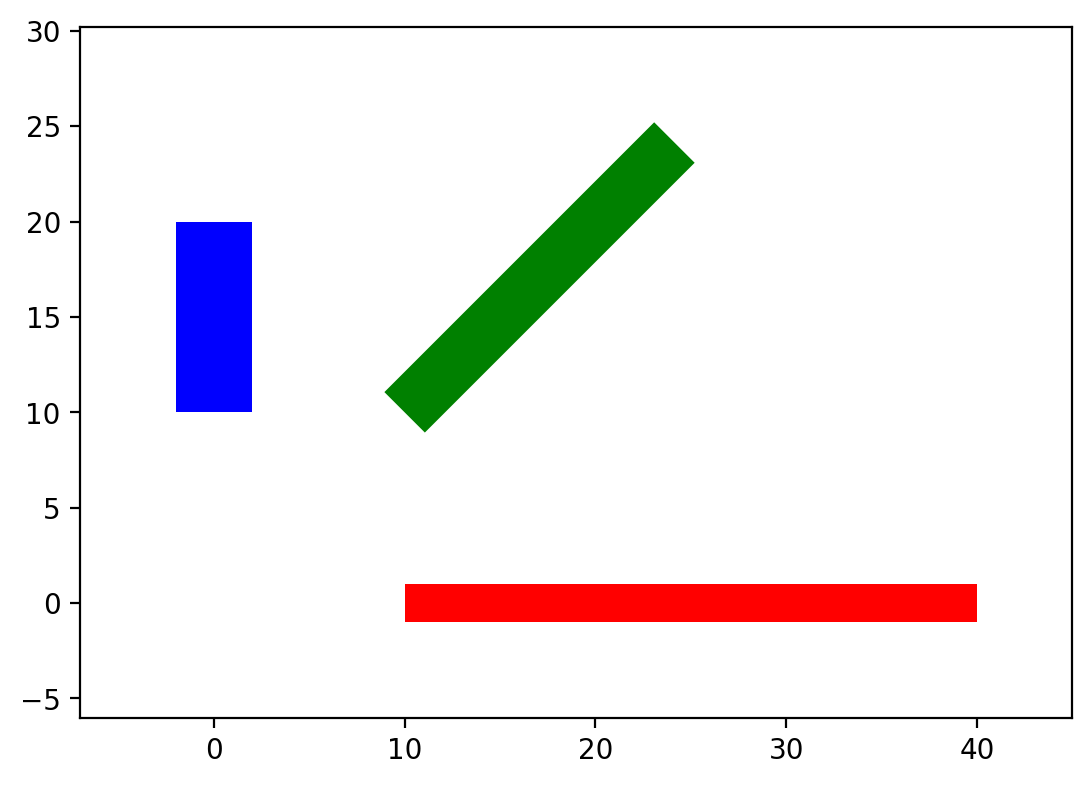
Waveguides are the most basic structures of integrated photonics circuits. To make the routing of these structures as easy as possible, gdshelpers has many different ways of creating waveguides. First of all, we have to define a port, meaning we have to give the origin, width and rotation of our waveguide. Now we can start with our routing. All in all the Waveguide class, which can be found in the waveguide package, contains 13 ways how to define waveguides. Let us start with the five simplest functions:
import numpy as np
from gdshelpers.geometry.chip import Cell
from gdshelpers.parts.port import Port
from gdshelpers.parts.waveguide import Waveguide

wg_1 = Waveguide.make_at_port(Port((0, 0), angle=-np.pi / 2, width=1.3))
wg_1.add_straight_segment(length=30)

wg_2 = Waveguide.make_at_port(Port((5, 0), angle=-np.pi / 2, width=1.3))
wg_2.add_bend(angle=np.pi / 2, radius=30)

wg_3 = Waveguide.make_at_port(Port((40, 0), angle=-np.pi / 2, width=1.3))
wg_3.add_straight_segment_until_y(y=-20)

wg_4 = Waveguide.make_at_port(Port((0, 5), angle=0, width=1.3))
wg_4.add_straight_segment_until_x(x=20)

wg_5 = Waveguide.make_at_port(Port((45, 0), angle=-np.pi / 4, width=1.3))
wg_5.add_arc(final_angle=-np.pi / 2, radius=30)

cell = Cell('CELL')
cell.add_to_layer(1, wg_1)  # red
cell.add_to_layer(2, wg_2)  # green
cell.add_to_layer(3, wg_3)  # blue
cell.add_to_layer(4, wg_4)  # teal
cell.add_to_layer(5, wg_5)  # pink
cell.show()
(Source code, png, hires.png, pdf)
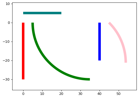
The most basic function is add_straight_segment, which adds a waveguide with a given length. Apart from the length we can also define the final width of the waveguide, which is not done in this example. To add bends to our routing, we can make use of the function add_bend. Parameters are the bend angle (as always in radiant) and the bend radius. Sometimes we don’t know how long a waveguide has to be or the starting position is unknown and we want to end at a certain position. In this case we can use the add_straight_segment_until_x/y function, which adds a waveguide with a length such that it terminates at the defined x/y position. Similarly, if the starting angle is not known and we want to add a bend which terminates in a certain angle, we can use the add_arc function.
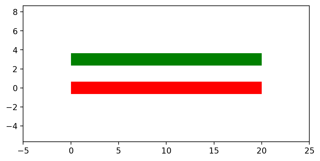
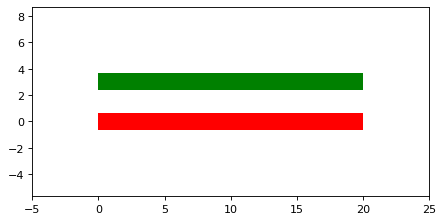
Note that there are two ways how to start a waveguide. First, we can call the make_at_port function, as it was done before. In addition, we can also initialize the waveguide by calling the constructor of the waveguide class:
from gdshelpers.geometry.chip import Cell
from gdshelpers.parts.waveguide import Waveguide
from gdshelpers.parts import Port

waveguide_1 = Waveguide.make_at_port(Port(origin=(0, 0), angle=0, width=1.3))
waveguide_1.add_straight_segment(length=20)

waveguide_2 = Waveguide(origin=(0, 3), angle=0, width=1.3)
waveguide_2.add_straight_segment(length=20)

cell = Cell('CELL')
cell.add_to_layer(1, waveguide_1)  # red
cell.add_to_layer(2, waveguide_2)  # green
cell.show()
(Source code, png, hires.png, pdf)
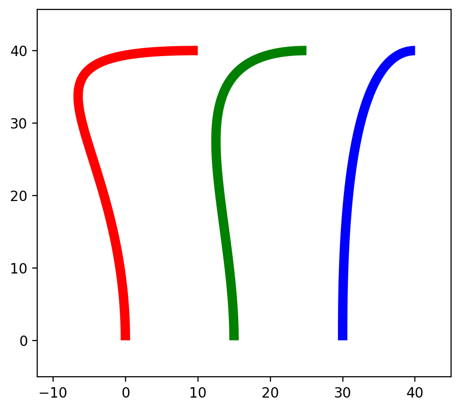
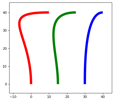
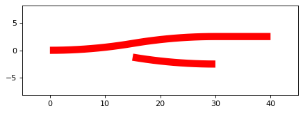
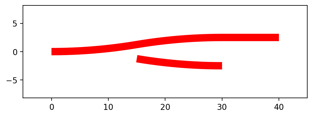
The library contains also more complex routing like Bezier curves oder parameterized paths. One way to create such a path is using the add_bezier_to function. In this case we have to define the final coordinates, the final angle and the bend strength of the curve.
import numpy as np
from gdshelpers.geometry.chip import Cell
from gdshelpers.parts.port import Port
from gdshelpers.parts.waveguide import Waveguide

wg_1 = Waveguide.make_at_port(Port((0, 0), angle=np.pi / 2, width=1.3))
wg_1.add_bezier_to(final_coordinates=(10, 40), final_angle=0, bend_strength=30)

wg_2 = Waveguide.make_at_port(Port((15, 0), angle=np.pi / 2, width=1.3))
wg_2.add_bezier_to(final_coordinates=(25, 40), final_angle=0, bend_strength=20)

wg_3 = Waveguide.make_at_port(Port((30, 0), angle=np.pi / 2, width=1.3))
wg_3.add_bezier_to(final_coordinates=(40, 40), final_angle=0, bend_strength=10)

cell = Cell('CELL')
cell.add_to_layer(1, wg_1)  # red
cell.add_to_layer(2, wg_2)  # green
cell.add_to_layer(3, wg_3)  # blue
cell.show()
(Source code, png, hires.png, pdf)
A second way is using the add_cubic_bezier_path, in which case the curve can be shaped with four control points.
import numpy as np
from gdshelpers.geometry.chip import Cell
from gdshelpers.parts.port import Port
from gdshelpers.parts.waveguide import Waveguide

wg_1 = Waveguide.make_at_port(Port(origin=(0, 0), angle=0, width=0.2))
wg_1.add_cubic_bezier_path(p0=(0, 0), p1=(0, 5), p2=(5, 10), p3=(5, 0))

wg_2 = Waveguide.make_at_port(Port(origin=(7, 0), angle=0, width=0.2))
wg_2.add_cubic_bezier_path(p0=(0, 0), p1=(0, 10), p2=(5, 15), p3=(5, 0))

wg_3 = Waveguide.make_at_port(Port(origin=(14, 0), angle=-np.pi / 2, width=0.2))
wg_3.add_cubic_bezier_path(p0=(0, 0), p1=(0, 5), p2=(5, 10), p3=(5, 0))

cell = Cell('CELL')
cell.add_to_layer(1, wg_1)  # red
cell.add_to_layer(2, wg_2)  # green
cell.add_to_layer(3, wg_3)  # blue
cell.show()
(Source code, png, hires.png, pdf)
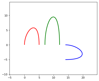
At this point we are not going into much more detail about the mathematical background and the meaning of the four points which define the Bezier curve, since enough good literature can be found the in the internet. If you are interested, read it ;)
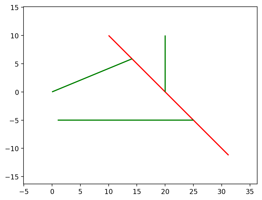
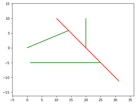
The last function to create waveguides is add_straight_segment_to_intersection. From a port a straight line is created, which continues as long as it does not intersect with a second line. This intersection line is defined in the function add_straight_segment_to_intersection. Note that this line continues in both directions indefinitely long. For visualization purposes, this intersection line is added in red to our design.
import numpy as np
from gdshelpers.geometry.chip import Cell
from gdshelpers.parts.port import Port
from gdshelpers.parts.waveguide import Waveguide

int_line = Waveguide.make_at_port(Port(origin=(10, 10), angle=-np.pi / 4, width=0.2))
int_line.add_straight_segment(length=30)

wg_1 = Waveguide.make_at_port(Port(origin=(0, 0), angle=np.pi / 8, width=0.2))
wg_1.add_straight_segment_to_intersection(line_origin=(10, 10), line_angle=-np.pi / 4)

wg_2 = Waveguide.make_at_port(Port(origin=(1, -5), angle=0, width=0.2))
wg_2.add_straight_segment_to_intersection(line_origin=(10, 10), line_angle=-np.pi / 4)

wg_3 = Waveguide.make_at_port(Port(origin=(20, 10), angle=-np.pi / 2, width=0.2))
wg_3.add_straight_segment_to_intersection(line_origin=(10, 10), line_angle=-np.pi / 4)

cell = Cell('CELL')
cell.add_to_layer(1, int_line)  # red
cell.add_to_layer(2, wg_1)  # green
cell.add_to_layer(2, wg_2)  # green
cell.add_to_layer(2, wg_3)  # green
cell.show()
(Source code, png, hires.png, pdf)
Slot waveguides
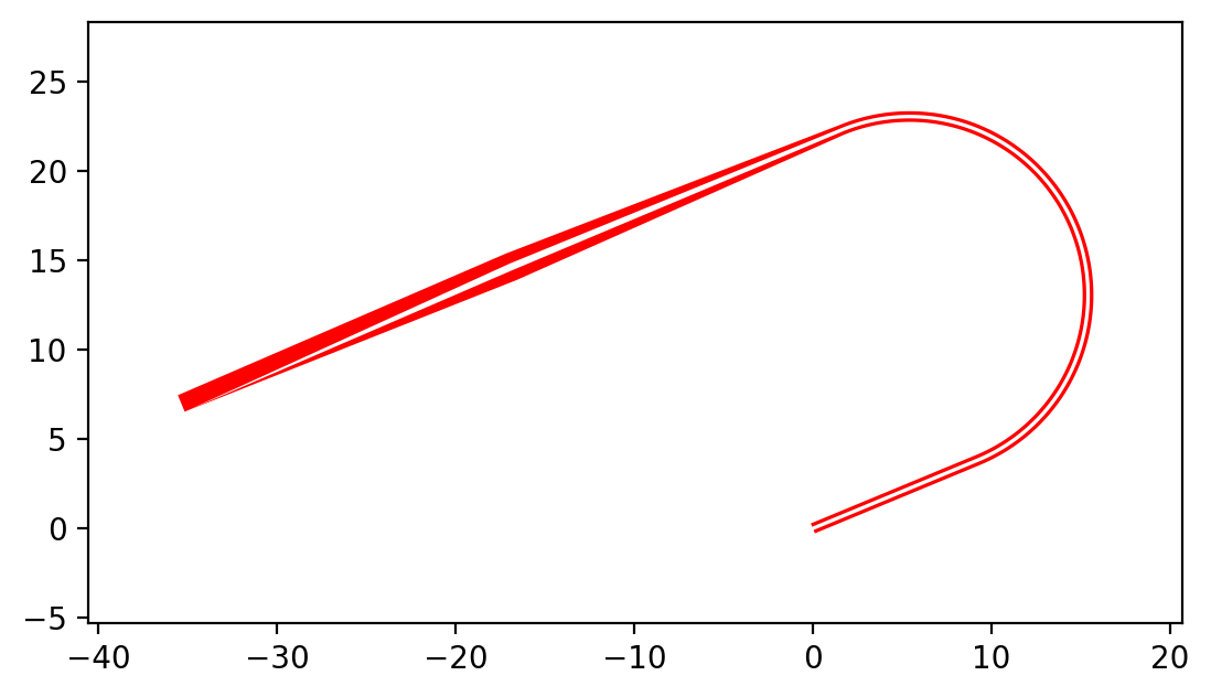
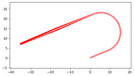
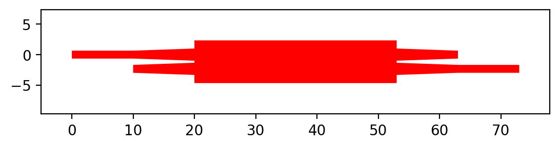
Alternatively, the width can also be an array for describing the dimensions of slot/coplanar waveguides. The array has the format [rail_width_1, slot_width_1, rail_width_2, …], where the rail_widths describe the widths of the rails and the widths of the slots are defined by the slot_widths. This array can also end with a slot_width, which would lead to an asymmetry with respect to the center. This can e.g. be useful for tapering between single waveguides and slot waveguides.
import numpy as np
from gdshelpers.geometry.chip import Cell
from gdshelpers.parts.port import Port
from gdshelpers.parts.waveguide import Waveguide

wg_1 = Waveguide.make_at_port(Port(origin=(0, 0), angle=np.pi / 8, width=[0.2,0.2,0.2])) # array as width -> slot waveguide
wg_1.add_straight_segment(10)
wg_1.add_bend(np.pi, 10)
wg_1.add_straight_segment(20, final_width=np.array([0.6,0.4,0.6])) # tapering between two slot waveguides
wg_1.add_straight_segment(20, final_width=np.array([0,0,1])) # tapering to a ridge waveguide

cell = Cell('CELL')
cell.add_to_layer(1, wg_1)  # red
cell.show()
(Source code, png, hires.png, pdf)
Beam splitters
Beam splitters are used to split a beam in two parts. They are quite important for photonic circuits and are essential for interferometers. Three different types of beam splitters can be found in the gdshelpers library: Y-Splitters, Multimode Interferometers (MMIs) and Directional Couplers. Their corresponding classes Splitter, MMI and DirectionalCoupler can be found in the splitter package.
Y-Splitters
First, let us have a look at the Y-splitter. They have one input port and two output ports. If we want to create the splitter at an existing waveguide, we can use the functions make_at_root_port, make_at_left_branch_port or make_at_right_branch_port. To continue our waveguide from the splitter, we can address the left output port left_branch_port or the right output port right_branch_port of the splitter.
from gdshelpers.geometry.chip import Cell
from gdshelpers.geometry import geometric_union
from gdshelpers.parts.waveguide import Waveguide
from gdshelpers.parts.splitter import Splitter

splitter = Splitter(origin=(0, 0), angle=0, total_length=30, wg_width_root=1.3, sep=5)
wg = Waveguide.make_at_port(splitter.left_branch_port)
wg.add_straight_segment(length=10)

cell = Cell('CELL')
cell.add_to_layer(1, splitter, wg)  # red
cell.show()
(Source code, png, hires.png, pdf)

Multimode Interferometers
In contrast to the Y-splitters, MMIs can have an arbitrary number of input and output ports. However, typically only 2x2 or 1x2 MMIs are used. As before, it is a good idea to have a look at an example:
from gdshelpers.geometry.chip import Cell
from gdshelpers.parts.waveguide import Waveguide
from gdshelpers.parts import Port
from gdshelpers.parts.splitter import MMI

waveguide_1 = Waveguide.make_at_port(Port((0, 0), 0, 1.3))
waveguide_1.add_straight_segment(length=10)
mmi = MMI.make_at_port(port=waveguide_1.current_port, length=33, width=7, num_inputs=2, num_outputs=2, pos='i0')
waveguide_2 = Waveguide.make_at_port(mmi.output_ports[0])
waveguide_2.add_straight_segment(length=10)

cell = Cell('CELL')
cell.add_to_layer(1, waveguide_1, mmi, waveguide_2)
cell.show()
(Source code, png, hires.png, pdf)
The first parameter of the the function MMI.make_at_port() defines the port of the MMI, meaning where the MMI is created and its rotation. The length and the width of the MMI
are defined by the second and third parameter. Choosing these parameters correctly is essential to achieve a good transmission and the desired splitting ration.
Last but not least, we have to define the number of input and output ports, which are given by the last two parameters of the function.
Apart from these parameters, the taper length and width can be optimized in order to increase the transmission. By default they are set to 10 um and 2 um.
As it can be seen, we have created a 2x2 MMI. At the moment, our input waveguide terminates in the upper input of the MMI. If we want it to terminate in the lower input, we have to change the position parameter to i1. Similarly, if we want to create a waveguide at the upper output, we have to replace mmi.output_ports[0] by mmi.output_ports[1].
Directional Couplers
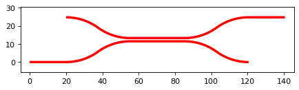
The last beam splitter we want to talk about is the directional coupler. It consists of two waveguides which are guided close to each other over a certain interaction length. As a consequence, we always have two input and two output ports. To make use of this coupler, we have to import the DirectionalCoupler class from the splitter library.
from gdshelpers.geometry.chip import Cell
from gdshelpers.parts.waveguide import Waveguide
from gdshelpers.parts import Port
from gdshelpers.parts.splitter import DirectionalCoupler

waveguide_1 = Waveguide.make_at_port(port=Port((0, 0), angle=0, width=1.3))
waveguide_1.add_straight_segment(length=20)
DC = DirectionalCoupler.make_at_port(port=waveguide_1.current_port, length=30, gap=0.5, bend_radius=30, which=0)
waveguide_2 = Waveguide.make_at_port(DC.right_ports[1])
waveguide_2.add_straight_segment(length=20)

cell = Cell('CELL')
cell.add_to_layer(1, waveguide_1, DC, waveguide_2)
cell.show()
(Source code, png, hires.png, pdf)

The origin of the coupler, the rotation and the width of the waveguides are tuned by the port parameter. Changing the width parameter we can decide whether we start at the lower (which = 0) or upper (which = 1)input. If we want our second waveguide to start at the other output of the coupler, we just have to replace right_ports[1] by right_ports[0].
Grating Coupler
To couple light in our photonic circuits, grating coupler are of quite often the coupler of choice. Of course, these structures can be found in the gdshelpers library. To create such a coupler, first we have to import the GratingCoupler class. To start a waveguide from the coupler, we can make use of the gc.port parameter of the GratingCoupler class
import numpy as np
from gdshelpers.geometry.chip import Cell
from gdshelpers.parts.waveguide import Waveguide
from gdshelpers.parts.coupler import GratingCoupler
coupler_params = {
'width': 1.3,
'full_opening_angle': np.deg2rad(40),
'grating_period': 1.155,
'grating_ff': 0.85,
'n_gratings': 20,
'taper_length': 16.
}
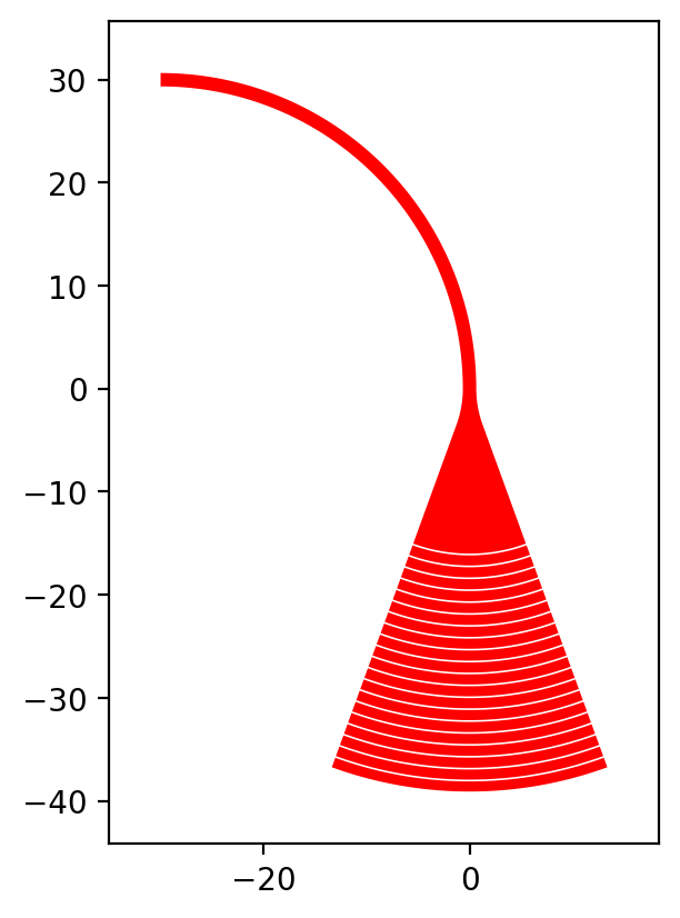
gc = GratingCoupler.make_traditional_coupler(origin=(0, 0), **coupler_params)
wg = Waveguide.make_at_port(gc.port)
wg.add_bend(np.pi / 2, radius=30)
cell = Cell('CELL')
cell.add_to_layer(1, wg, gc)
cell.show()
(Source code, png, hires.png, pdf)

Text
It is often quite useful to add text to the design, for example to identify a device under the microscope. Adding text is quite easy. We just have to import
the class Text() from the package gdshelpers.parts.text(). The second step is to call the constructor of the class Text().
import numpy as np
from gdshelpers.geometry.chip import Cell
from gdshelpers.parts.text import Text
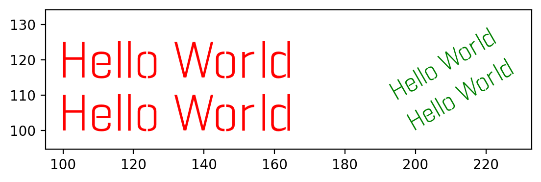
text_1 = Text(origin=[100, 100], height=10, text='Hello World\nHello World', alignment='left-bottom')
text_2 = Text(origin=[200, 100], height=5, text='Hello World\nHello World', alignment='left-bottom', angle=np.pi / 6, line_spacing=2)
cell = Cell('CELL')
cell.add_to_layer(1, text_1) # red
cell.add_to_layer(2, text_2) # green
cell.show()
(Source code, png, hires.png, pdf)
The first parameter origin denotes the position and the height of the text can be set by the second parameter height. The text itself can be given by the third parameter text. In addition, optional parameters as alignment, angle and line_spacing can be used the align, rotate the text and to vary the spacing between the lines.
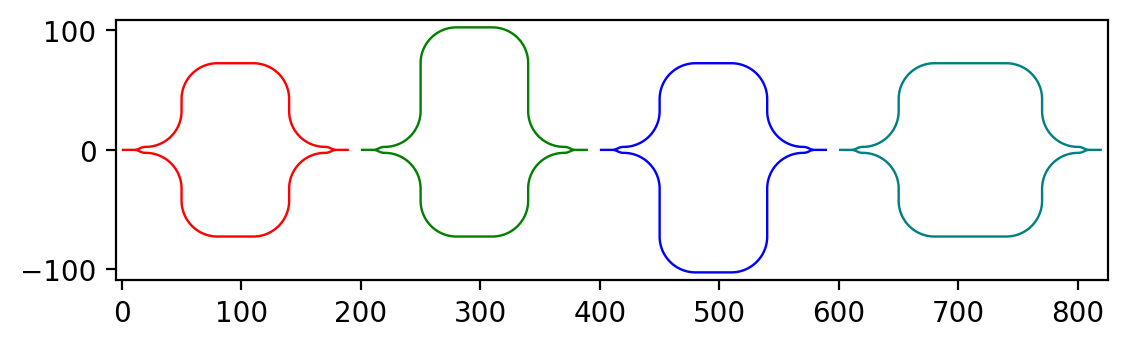
Mach Zehnder Interferometers
from gdshelpers.geometry.chip import Cell
from gdshelpers.parts.port import Port
from gdshelpers.parts.waveguide import Waveguide
from gdshelpers.parts.interferometer import MachZehnderInterferometer
wg_1 = Waveguide.make_at_port(Port((0, 0), angle=0, width=2))
wg_1.add_straight_segment(10)
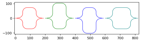
mzi_1 = MachZehnderInterferometer.make_at_port(port=wg_1.current_port, splitter_length=10, splitter_separation=5,
bend_radius=30, upper_vertical_length=10, lower_vertical_length=10,
horizontal_length=30)
wg_2 = Waveguide.make_at_port(mzi_1.port)
wg_2.add_straight_segment(10)
wg_3 = Waveguide.make_at_port(Port((200, 0), angle=0, width=2))
wg_3.add_straight_segment(10)
mzi_2 = MachZehnderInterferometer.make_at_port(port=wg_3.current_port, splitter_length=10, splitter_separation=5,
bend_radius=30, upper_vertical_length=40, lower_vertical_length=10,
horizontal_length=30)
wg_4 = Waveguide.make_at_port(mzi_2.port)
wg_4.add_straight_segment(10)
wg_5 = Waveguide.make_at_port(Port((400, 0), angle=0, width=2))
wg_5.add_straight_segment(10)
mzi_3 = MachZehnderInterferometer.make_at_port(port=wg_5.current_port, splitter_length=10, splitter_separation=5,
bend_radius=30, upper_vertical_length=10, lower_vertical_length=40,
horizontal_length=30)
wg_6 = Waveguide.make_at_port(mzi_3.port)
wg_6.add_straight_segment(10)
wg_7 = Waveguide.make_at_port(Port((600, 0), angle=0, width=2))
wg_7.add_straight_segment(10)
mzi_4 = MachZehnderInterferometer.make_at_port(port=wg_7.current_port, splitter_length=10, splitter_separation=5,
bend_radius=30, upper_vertical_length=10, lower_vertical_length=10,
horizontal_length=60)
wg_8 = Waveguide.make_at_port(mzi_4.port)
wg_8.add_straight_segment(10)
cell = Cell('CELL')
cell.add_to_layer(1, wg_1, wg_2, mzi_1) # red
cell.add_to_layer(2, wg_3, wg_4, mzi_2) # green
cell.add_to_layer(3, wg_5, wg_6, mzi_3) # blue
cell.add_to_layer(4, wg_7, wg_8, mzi_4) # teal
cell.show()
(Source code, png, hires.png, pdf)

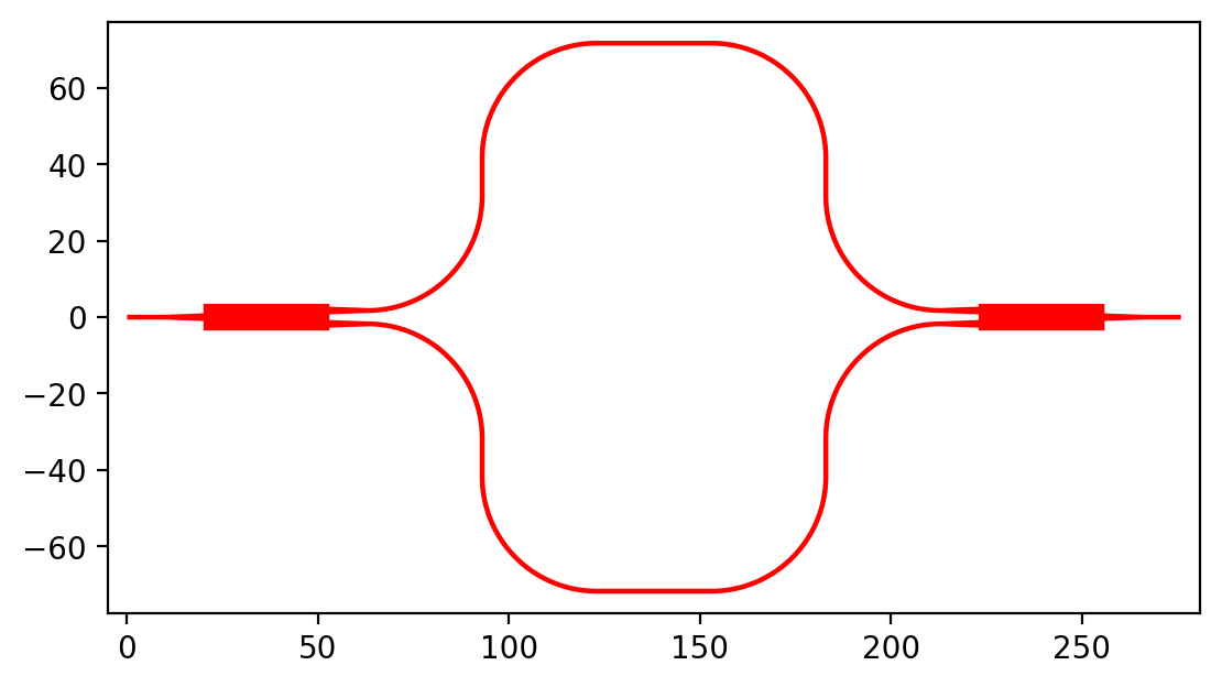
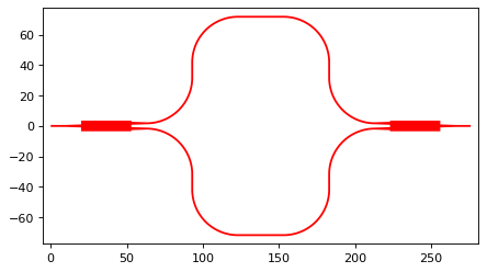
In this case a Y-Splitter was used. However, as MMIs are also frequently used, it makes sense to integrate them in this library. For this reason you can find a Mach Zehnder Interferometers
from gdshelpers.geometry.chip import Cell
from gdshelpers.parts.port import Port
from gdshelpers.parts.waveguide import Waveguide
from gdshelpers.parts.interferometer import MachZehnderInterferometerMMI

wg_1 = Waveguide.make_at_port(Port(origin=(0, 0), angle=0, width=1.3))
wg_1.add_straight_segment(length=20)
mzi_1 = MachZehnderInterferometerMMI.make_at_port(port=wg_1.current_port, splitter_length=33, splitter_width=7,
                                                                                                  bend_radius=30, upper_vertical_length=10, lower_vertical_length=10,
                                                                                                  horizontal_length=30)
wg_2 = Waveguide.make_at_port(port=mzi_1.port)
wg_2.add_straight_segment(length=20)

cell = Cell('CELL')
cell.add_to_layer(1, wg_1, wg_2, mzi_1)
cell.show()
(Source code, png, hires.png, pdf)
Resonators
Ring Resonators
from gdshelpers.geometry.chip import Cell
from gdshelpers.parts.resonator import RingResonator
from gdshelpers.parts.port import Port
from gdshelpers.parts.waveguide import Waveguide

waveguide_1 = Waveguide.make_at_port(Port([0, 0], 0, 1.3))
waveguide_1.add_straight_segment(100)
resonator_1 = RingResonator.make_at_port(waveguide_1.current_port, gap=1, radius=50)
waveguide_1.add_straight_segment(100)

waveguide_2 = Waveguide.make_at_port(Port([250, 0], 0, 1.3))
waveguide_2.add_straight_segment(100)
resonator_2 = RingResonator.make_at_port(waveguide_2.current_port, gap=-0.5, radius=40)
waveguide_2.add_straight_segment(100)

cell = Cell('CELL')
cell.add_to_layer(1, waveguide_1, resonator_1) # red
cell.add_to_layer(2, waveguide_2, resonator_2) # green
cell.show()
(Source code, png, hires.png, pdf)
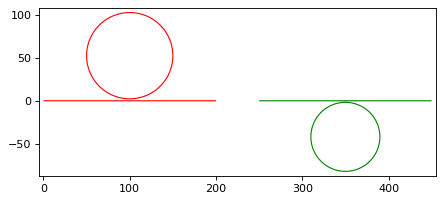
Apart from the port (origin, width and angle), the ring resonator is defined by the gap between waveguide and the ring as well as the radius of the ring.
Ports
Ports are constructs to make things easier. They are not visible in the final .gds file. Each port has three different properties:
- Origin
- Width
- Rotation
The width defines the width of all structures (e.g. waveguides) that start from this port. As always, the rotation is given in radiant and is calculated counterclockwise.
import numpy as np
from gdshelpers.geometry.chip import Cell
from gdshelpers.parts.port import Port
from gdshelpers.parts.waveguide import Waveguide

wg_1 = Waveguide.make_at_port(Port(origin=[10, 0], angle=0, width=2))
wg_1.add_straight_segment(length=30)

wg_2 = Waveguide.make_at_port(Port(origin=[10, 10], angle=np.pi / 4, width=3))
wg_2.add_straight_segment(length=20)

wg_3 = Waveguide.make_at_port(Port(origin=[0, 10], angle=np.pi / 2, width=4))
wg_3.add_straight_segment(length=10)

cell = Cell('CELL')
cell.add_to_layer(1, wg_1) # red
cell.add_to_layer(2, wg_2) # green
cell.add_to_layer(3, wg_3) # blue
cell.show()
(Source code, png, hires.png, pdf)

Many structures (e.g. waveguides, couplers, splitters) have a port, current_port or output_ports option. This can be used to start a new structure, e.g. a waveguide, from an old structure:
import numpy as np
from gdshelpers.geometry.chip import Cell
from gdshelpers.parts.waveguide import Waveguide
from gdshelpers.parts.coupler import GratingCoupler

coupler_params = {
        'width': 1.3,
        'full_opening_angle': np.deg2rad(40),
        'grating_period': 1.155,
        'grating_ff': 0.85,
        'n_gratings': 20,
        'taper_length': 16.
}

gc = GratingCoupler.make_traditional_coupler(origin=(0, 0), **coupler_params)

wg = Waveguide.make_at_port(gc.port)
wg.add_bend(np.pi / 2, radius=30)

cell = Cell('CELL')
cell.add_to_layer(1, wg, gc)
cell.show()
(Source code, png, hires.png, pdf)

Optical Codes
QR Codes
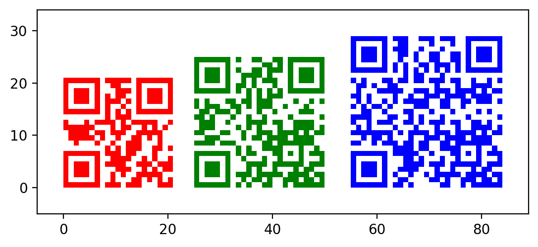
Sometimes it can be useful to add QRCodes to a design. For example to create a link to a homepage. To add such a code, we have to import the QRCode class from the optical_codes package.
from gdshelpers.geometry.chip import Cell
from gdshelpers.parts.optical_codes import QRCode

qr_code_1 = QRCode(origin=[0, 0], data='A0.0', box_size=1.0, version=1, error_correction=QRCode.ERROR_CORRECT_M)
qr_code_2 = QRCode(origin=[25, 0], data='A0.0', box_size=1.0, version=2, error_correction=QRCode.ERROR_CORRECT_M)
qr_code_3 = QRCode(origin=[55, 0], data='A0.0', box_size=1.0, version=3, error_correction=QRCode.ERROR_CORRECT_M)

cell = Cell('CELL')
cell.add_to_layer(1, qr_code_1) # red
cell.add_to_layer(2, qr_code_2) # green
cell.add_to_layer(3, qr_code_3) # blue
cell.show()
(Source code, png, hires.png, pdf)

As always, the origin defines the point where the pattern is created. The data to be encoded is defined by the second parameter and the size of each element is defined by the box_size parameter.
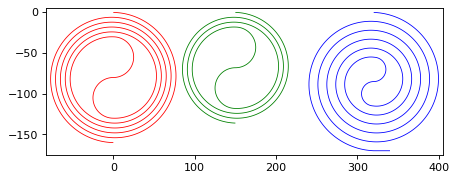
Spiral
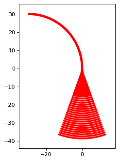
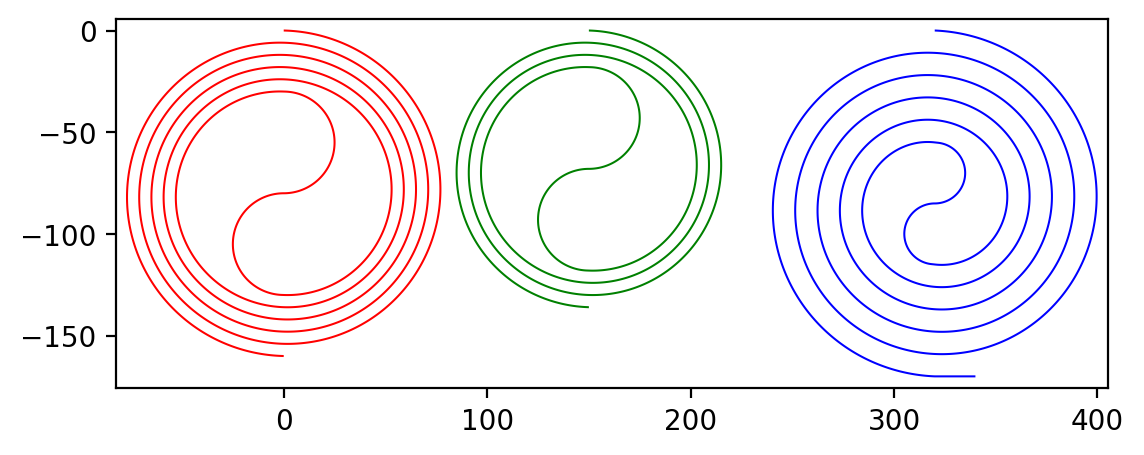
Sometimes long waveguides are needed, for example to determine the loss per length. Spirals are useful geometries for this case. For this purpose we can make use of the Spiral class, which can be found in the spiral package. A spiral is defined by four parameters: Port (origin, angle, width), number of turns, distance between two neighboring turns and the inner gap. At the end of the spiral we can continue our waveguide by referring to its output port out_port. Note that the spiral can not be defined over its length. However, we can readout the length with the length property.
from gdshelpers.geometry.chip import Cell
from gdshelpers.parts.port import Port
from gdshelpers.parts.spiral import Spiral
from gdshelpers.parts.waveguide import Waveguide

spiral_1 = Spiral.make_at_port(Port(origin=(0, 0), angle=0, width=1), num=5, gap=5, inner_gap=50)
spiral_2 = Spiral.make_at_port(Port(origin=(150, 0), angle=0, width=1), num=3, gap=5, inner_gap=50)
spiral_3 = Spiral.make_at_port(Port(origin=(320, 0), angle=0, width=1), num=5, gap=10, inner_gap=30)
length = spiral_3.length
wg = Waveguide.make_at_port(spiral_3.out_port)
wg.add_straight_segment(20)

cell = Cell('Spiral')
cell.add_to_layer(1, spiral_1)  # red
cell.add_to_layer(2, spiral_2)  # green
cell.add_to_layer(3, spiral_3, wg)  # blue
cell.show()
(Source code, png, hires.png, pdf)
