Modifier
From negative layout to postive layout
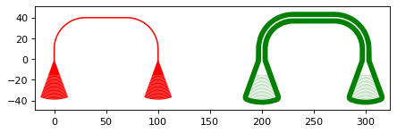
Sometimes, using positive resist to pattern the waveguides gives better results compared to negative resist. To make this way of designing the structures
as easy as possible, we implemented a function called convert_to_positve_resist(). Apart from the defining the structure itself,
the only parameter that has to be given is the buffer radius. Here is a short example of two photonic routings,
one patterned with negative (red) and one patterned with positive (green) resist:
import numpy as np
from gdshelpers.geometry.chip import Cell
from gdshelpers.parts.waveguide import Waveguide
from gdshelpers.parts.coupler import GratingCoupler
from gdshelpers.helpers.positive_resist import convert_to_positive_resist

coupler_params = {
    'width': 1.3,
    'full_opening_angle': np.deg2rad(40),
    'grating_period': 1.155,
    'grating_ff': 0.85,
    'n_gratings': 20,
    'taper_length': 16.
}

# negative resist
left_coupler_1 = GratingCoupler.make_traditional_coupler((0,0), **coupler_params)
right_coupler_1 = GratingCoupler.make_traditional_coupler((100,0), **coupler_params)

wg_1 = Waveguide.make_at_port(left_coupler_1.port)
wg_1.add_straight_segment(10)
wg_1.add_bend(-np.pi / 2, 30)
wg_1.add_straight_segment_until_x(right_coupler_1.port.x - 30)
wg_1.add_bend(-np.pi / 2, 30)
wg_1.add_straight_segment(10)

# positive resist
left_coupler_2 = GratingCoupler.make_traditional_coupler((200,0), **coupler_params)
right_coupler_2 = GratingCoupler.make_traditional_coupler((300,0), **coupler_params)

wg_2 = Waveguide.make_at_port(left_coupler_2.port)
wg_2.add_straight_segment(10)
wg_2.add_bend(-np.pi / 2, 30)
wg_2.add_straight_segment_until_x(right_coupler_2.port.x - 30)
wg_2.add_bend(-np.pi / 2, 30)
wg_2.add_straight_segment(10)

cell = Cell('SIMPLE_DEVICE')
cell.add_to_layer(1, left_coupler_1, wg_1, right_coupler_1)
cell.add_to_layer(2, convert_to_positive_resist(parts=[wg_2, left_coupler_2, right_coupler_2], buffer_radius=5))
cell.show()
(Source code, png, hires.png, pdf)

As it can be seen, the workflow is exactly the same as for negative resist and only one additional function has to be added. Of course, this does also work for more complex designs.
Creating holes for underetching
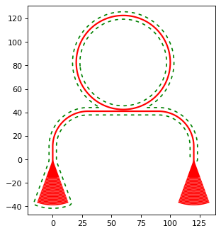
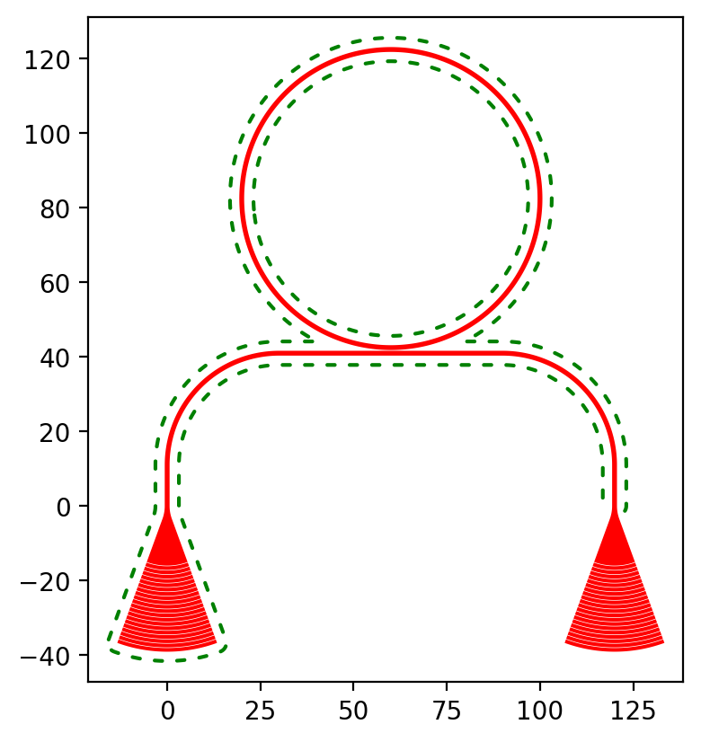
To creates holes around defined parts, which can be used for underetching processes, we implemented a create_holes_for_under_etching() function.
For this example, let us consider a grating coupler, a waveguide, a ring resonator and a second grating coupler.
First, we have to define the parts which shall be underetched, in this case the left grating coupler, waveguide and ring resonator.
If the complete structure is underetched, then you will not notice any problems.
However, if one part of your structure is not underetched, for example the right grating coupler, then you might get a collision between the
photonics layer and the hole layer. For this reason, in addition to the underetching_parts,
we have to define the complete_structure, which is used to prevent overlapping. While the underetching_parts contains the left grating coupler, waveguide and resonator,
the complete_structure contains the underetching_parts and additonally, the second grating coupler.
Finally, the radius, distance, spacing and and length of the holes ca be adjusted using the corresponding parameters.
import numpy as np
from gdshelpers.geometry import geometric_union
from gdshelpers.parts.coupler import GratingCoupler
from gdshelpers.geometry.chip import Cell
from gdshelpers.parts.waveguide import Waveguide
from gdshelpers.parts.resonator import RingResonator
from gdshelpers.helpers.under_etching import create_holes_for_under_etching

coupler_params = {
    'width': 1.3,
    'full_opening_angle': np.deg2rad(40),
    'grating_period': 1.155,
    'grating_ff': 0.85,
    'n_gratings': 20,
    'taper_length': 16.
}

# ==== create some sample structures (straight line with ring resonator)
coupler_1 = GratingCoupler.make_traditional_coupler((0,0), **coupler_params)
wg_1 = Waveguide.make_at_port(coupler_1.port)
wg_1.add_straight_segment(11)
wg_1.add_bend(-np.pi / 2, 30)
wg_1.add_straight_segment(30)
resonator = RingResonator.make_at_port(port=wg_1.current_port, gap=0.2, radius=40)
wg_1.add_straight_segment(30)
wg_1.add_bend(-np.pi / 2, 30)
wg_1.add_straight_segment(11)
coupler_2 = GratingCoupler.make_traditional_coupler(wg_1.current_port.origin, **coupler_params)

underetching_parts = geometric_union([wg_1, resonator, coupler_1])
complete_structure = geometric_union([underetching_parts, coupler_2])
# create the holes with a radius of 0.5 microns, a distance of 2 microns to the structure borders and
# a distance of 2 microns between the holes
holes = create_holes_for_under_etching(underetch_parts=underetching_parts, complete_structure=complete_structure,
                                       hole_radius=0.5, hole_distance=2, hole_spacing=3, hole_length=3)

# create a cell with the structures in layer 1 and the holes in layer 2
cell = Cell('CELL')
cell.add_to_layer(1, complete_structure)
cell.add_to_layer(2, holes)
cell.show()
(Source code, png, hires.png, pdf)
